 |
IceCube display
LED display to show IceCube event data
|


|
|
IceCube display
LED display to show IceCube event data
|
|

The table-top IceTop event display developed at UGent was the origin of this firmware project. It is a portable display that uses strips with 30 or 60 LED modules per meter, resulting in acceptable dimensions that facilitate it being caried around and used e.g. for classes on astroparticle physics. It is driven by a self-designed display controller, built around the ATmega32U4 microcontroller.
Due to the fine pitch of the 60 LED/m strips, the in-fill stations have not been included in the small verison of the display. They can be included if the display uses a 30 LED/m pitch, and the firmware is able to deal with these different configurations.
The LED strips contain APA-102C devices which were selected due to their adjustable brightness setting and clocked data input lines. This results in less stringent timing contraints for the controlling electronics, as the controller can decide how fast the data is clocked, and clock jitter is less of an issue.
The display has a number of input buttons and LEDs to interact with and relay status information to the user. The green Power LED indicates whether the display is receiving 5V power input. The orange USB activity LED will light up when there is a USB connection, and blink when there is bus activity, e.g. when display data is transmitted. Aside from Steamshovel connectivity, this display also supports stand-alone operation.
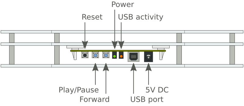
In stand-alone mode, when the display is not connected via USB and only powered on, the display can also show a number of IceTop events stored on the device itself. For every event, first a time-lapse will be shown, followed by an overview. The light intensity of the LEDs is related to the amount of light collected by the corresponding IceTop station, and the colour is related to the time when this light was collected. Red means early in the event, blue means late. After pressing either of the blue buttons, the display will start cycling through the 9 stored IceTop events. At any point, you can go to the next event using the Forward button. You can also pause an event overview by pressing Play/Pause during playback, or resume playback by pressing the button again when the display is paused.
First, three down-going events of increasing energy will be shown. Then come three slightly inclined events, and three events with large inclination, again each group with increasing energy. As the energy of the events increases, you will see that the part of the detector that is activated by the airshower also increases. Also, as the inclination of the showers increase, it becomes clear that the shower is actually contained in a moving surface when it hits the detector. Downgoing events activate the detector almost simultaneously, while inclined events seem move along the surface of the detector.
Building the firmware can only be done with avr-gcc. The firmware also uses avr-libc to provide a C implementation of low-level microcontroller features.
Three bytes of the LED information EEPROM are used to store display specific information:
| Address offset | Description |
|---|---|
| 0x20 + 0x0 | LED count: 78 for the small display, 81 for the large display |
| 0x20 + 0x1 | Supported LED type: see display_led_type_t |
| 0x20 + 0x2 | LED RGB order: see display_led_color_order_t |
Although currently stored in the firmware image, the LED mapping could be moved to the EEPROM for future displays. In this case up to 81 additional bytes of EEPROM can be used, starting from address 0x30.
The recommend way to upgrade the device firmware is via USB. To perform the upgrade, first power the device using the 5V power supply, and connect the display to the computer used to perform the upgrade via a USB cable. You should see the green and orange LED light up. The display now needs to be rebooted into firmware upgrade mode. To do this, press and hold the Forward button while pressing the reset button. After releasing reset, the Forward button can also be released and the display should now be in firmware upgrade mode. The green LED will still be on, but the orange LED will now be off.
When performing the lsusb command on Linux, you will now see the Atmel bootloader showing up in the listing:
$ lsusb | grep -e "Atmel"
Bus 001 Device 039: ID 03eb:2ff4 Atmel Corp. atmega32u4 DFU bootloader
After building the firmware from source, the new firmware can be uploaded using a custom make target:
make upload
If the firmware was provided as a pre-compiled binary file (e.g. as icetop_display.hex), you can upload the firmware using the avrdude command:
# When only one device is connected
avrdude -p ATMEGA32U4 -c flip1 -U flash:w:icetop_display.hex

# When multiple devices are connected (and ready to be programmed),
# you should also specify which port number to use (use lsusb to find out)
avrdude -p ATMEGA32U4 -c flip1 -P usb:001:039 -U flash:w:icetop_display.hex
The device can also be programmed using the ICSP header on the board. Note that any normal firmware upgrade can be performed via USB, so using the ICSP port is not the recommended way of upgrading your display! To access the ICSP header, the bottom plate of the device needs to be removed. Pin 1 of the header is marked with a slightly offset angle, and is next to the P3 marking. The VCC line of the ICSP header can be used to power the device, so make sure that the programmer's VCC line is either disconnected, or that the external power suppy is not used!
With an ICSP programmer, the flash and EEPROM will be erased prior to the device upgrade. It is recommended to configure the CMake system to generate the right EEPROM data and program the fuses and lock bits, the EEPROM, the program flash, and the bootloader flash. When performing the initial flash of the device after assembly, a complete chip erase should be performed beforehand to ensure the lock bits are reset and a new firmware can be flashed to the device.
Total: €110 (excl. VAT)
 1.8.13