24p POE+ 4sfp
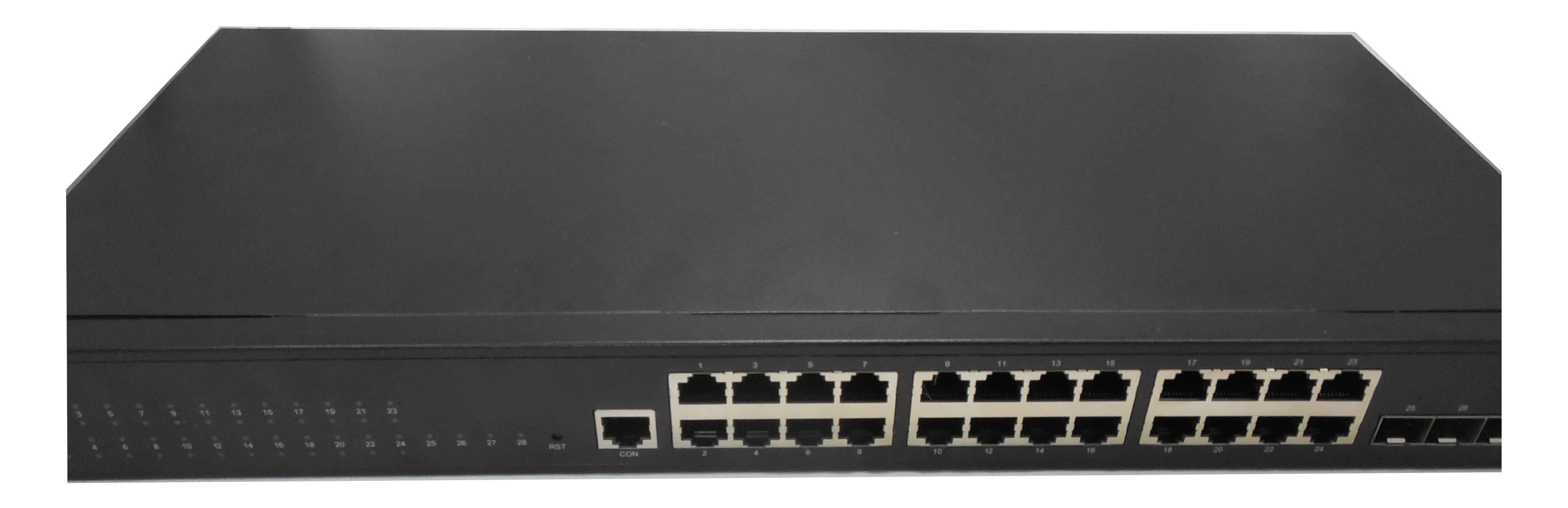
This is an Fullriver FR-S3128GT-370P2 managed multi-gigabit POE+ (370W) Ethernet switche.
Architecture Overview
The switch makes use of the various SerDeS units on the RTL9301.
| SDS | Use | Connection | port(s) |
|---|---|---|---|
| 0? | RTL8218D | QSGMII | 0 - 4 |
| 1? | RTL8218D | QSGMII | 5 - 7 |
| 2? | RTL8218D | XSGMII | 8 - 15 |
| 3? | RTL8218D | XSGMII | 16 - 23 |
| 4? | SFP+ | 10GBase-R | 24 |
| 6? | SFP+ | 10GBase-R | 25 |
| 8? | SFP+ | 10GBase-R | 26 |
| 9? | SFP+ | 10GBase-R | 27 |
Models
Hardware
- RTL9301 SoC
- Winbond W25Q256JV (256MB flash)
- Winbond W632GG6NB-1q (256MB DDR3 SDRAM)
- 3x RTL8218D 8x Gigabit PHY
- 3x RTL8238B POE controller
- Holtek HT32F50231 POE protocol-controller
- reset button
- power-led (pwr1, always not controllable)
- run-led (sys1, gpio0)
4 Uplink ports are SFP+ cages which support 10GBit Base-X mini GBIC modules.
Power is supplied via a 100V-24-V 10A standard IEC connector. A Serial header can be connected to from the outside of the switch trough the RJ45 'console' port with a standard cisco 'blue' pinout. Serial connection is via 115200 baud, 8N1.


OEM Firmware
OEM U-Boot environment
RTL9300# # printenv
baudrate=115200
boardmodel=RTL8393M_DEMO
bootcmd=boota
bootdelay=1
ethaddr=00:E0:4C:00:00:00
ipaddr=192.168.1.1
ledModeInitSkip=0
serverip=192.168.1.111
stderr=serial
stdin=serial
stdout=serial

Environment size: 217/65532 bytes
OEM SYS environment
RTL9300# # printsys
bootpartition=1
...<0xff>...
System information size: 4093/4096 bytes
OEM bootlog
U-Boot 2011.12.(3.6.7.55090) (Jan 11 2023 - 11:23:36)

Board: RTL9300 CPU:800MHz LX:175MHz DDR:600MHz
DRAM:  256 MB
SPI-F: WINBOND/EF4019/MMIO32-2/ModeC 1x32 MB (plr_flash_info @ 83f93cc4)
Loading 65536B env. variables from offset 0xe0000
Net:   Net Initialization Skipped
No ethernet found.
Hit Esc key to stop autoboot:  0
## dual_image_sel ... -1-1-1
## Booting image from partition ... 1
## Booting kernel from Legacy Image at 81000000 ...
   Image Name:   RTK_SDK
   Created:      2023-01-11  11:28:27 UTC
   Image Type:   MIPS Linux Kernel Image (lzma compressed)
   Data Size:    9173575 Bytes = 8.7 MB
   Load Address: 80000000
   Entry Point:  802b3350
   Verifying Checksum ... OK
   Uncompressing Kernel Image ... OK

Starting kernel ...


Loading drivers..................................OK
Loading basic manager applications...............OK
Loading L2 applications..........................OK
Loading L3 applications..........................OK
Loading manager applications.....................OK
Load successfully.

Username(1-64 chars):admin
Password(1-128 chars):admin

Switch>
OEM Flash layout
U-Boot
RTL9300# # flshow
=============== FLASH Partition Layout ===============
Index  Name       Size       Address
------------------------------------------------------
 0     LOADER     0xe0000    0xb4000000-0xb40dffff
 1     BDINFO     0x10000    0xb40e0000-0xb40effff
 2     SYSINFO    0x10000    0xb40f0000-0xb40fffff
 3     JFFS2_CFG  0x100000   0xb4100000-0xb41fffff
 4     JFFS2_LOG  0x400000   0xb4200000-0xb45fffff
 5     RUNTIME1   0xd00000   0xb4600000-0xb52fffff
 6     RUNTIME2   0xd00000   0xb5300000-0xb5ffffff
======================================================
GPIO's
By looking at 0xb8003300 from U-Boot, we can see the GPIO's toggling the bits. Inserting an SFP module into the SFP port triggers 'some' GPIO, either ABS or something else as the pinout doesn't seem to match exactly. TBC.
- GPIO00 sysled
- GPIO01 External watchdog disable (NC)
- GPIO02 External watchdog ping (NC)
- GPIO03 reset button
- GPIO04 GPIO I2C_CLK to fan controller (NC)
- GPIO05 GPIO I2C_DATA to fan controller (NC)
- GPIO06 EN PHY (NC)
- GPIO07 SDC
- GPIO08 port24 (sfp0) SDA
- GPIO09 port25 (sfp1) SDA
- GPIO10 port26 (sfp2) SDA
- GPIO11 port27 (sfp3) SDA
- GPIO12 port24 (sfp0) TXD
- GPIO13 port24 (sfp0) LOS
- GPIO14 port25 (sfp1) TXD
- GPIO15 port25 (sfp1) LOS
- GPIO16 port26 (sfp2) TXD
- GPIO17 port26 (sfp2) LOS
- GPIO18 port27 (sfp3) TXD
- GPIO19 port27 (sfp3) LOS
- GPIO20 has POE hardware board fitted
- GPIO21 - 23 Board ID
Connectors
Order of pinout is not the same for J1 and J2 …
J1 (connects to LED board)
- 1: VDD
- 2: GPIO00 (SYS_LED)
- 3: LED_CLK (rtl8231)
- 4: LED_DAT (rtl8231)
- 5: Reset (rtl8231)
- 6: GND
- 7: LED Latch (from POE controller?)
- 8: MOSI (from POE controller?)
- 9: LED Output enable (from POE controller?)
- 10: SCK (from POE controller?)
J2 (Connects to POE board)
- 1: VDD
- 2: VDD
- 3: JTAG_TDO
- 4: JTAG_TMS
- 5: JTAG_TCK
- 6: JTAG_TDI
- 7: GND
- 8: GND
- 9: MOSI (from POE controller?)
- 10: LED Latch (from POE controller?)
- 11: SCK (from POE controller?)
- 12: LED Output enable (from POE controller?)
Probably to test/sniff the POE leds and/or program the POE micro controller; though that one has its own pinout (J3) …
Notes
`rtk network on` in U-Boot sets all SPI pins to SPI pins, which breaks the reset GPIO. Use
'rtk network on; mw 0xbb0003a0 0x00340000; tftpboot; bootm'
instead