TP-Link T1600G-52PS v4
The TP-Link T1600G-52PS v4 48 + 4-port Gigabit L2 switch with PoE+, also called TL-SG2452P.
Note: the v4 (and possibly v3) boards in this series are RTL83xx-based. However v1 is based on the Broadcom BCM53344/BCM53346 chipset.
Hardware
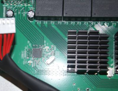
- RTL8393M SoC
- Winbond 25Q256JVFQ (32MB flash)
- SEC K4B2G1646 BYMA (256MB RAM)
- PoE daughter board:
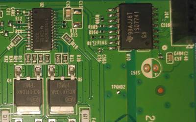
- TI 9BAJJ6T ISO7741 digital isolator
- 12× TI TPS23861PW PSE controller
4 Uplink ports are SFP cages which support 1000 Base-X mini GBIC modules.
Power is supplied via a 230 volt mains connector, with an internal power supply for 12 Volt and PoE+.
The board does not have a console connector, but there is an unpopulated header at the left side (front-facing). The Pinout is either TX-RX-GND-VCC or RX-TX-GND-VCC, this needs to be checked again. The connection parameters are 38400 8N1.
Board details
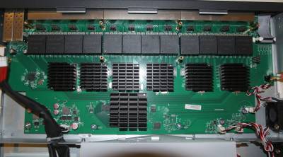
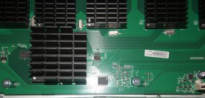
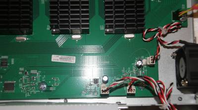
There is 1 main PCB and a small PCB with 13 shift register logic chips to control the LEDs (74HC164).
There are no ICs on the bottom side of the PCB.
Firmware
It ships with a bootloader based on Realtek's SDK for RTL83xx SoCs and Linux 2.6.32 based on Realtek's second generation SDK. It has a web interface for all management functions.
OpenWrt Support
OpenWrt support is currently WiP. There is serial access to the bootloader and the stock firmware image has been successfully decrypted. However, a new U-Boot is recommended for development. Otherwise, initramfs images can only be flashed by grounding the CLK pin of the flash chip at the right time during boot.
It might be possible to have upgrades from the stock web interface, but this depends on whether the RSA signature is actually verified or not - the relevant code is commented in the bootloader source code.
Compiling a new bootloader
In order to be able to boot an OpenWrt build, a new U-Boot with network support is required. This can be built from the GPL drop with the following commands:
- Patch package/zlib/zlib.mk and remove line
export LD_LIBRARY_PATH=/lib:$$LD_LIBRARY_PATH; $(MAKE1) -C $(@D) make O=t1600g-52ps-v4 tplink-t1600g-52ps-v4_defconfigmake O=t1600g-52ps-v4- u-boot.bin is at
tplink-t1600g-52ps-v4/images/u-boot.bin
There is no need to change anything in the source code, as debug is enabled by default. To flash it, a SOIC-16 clip and flashing tool is required - a cheap WCH340-based SPI flasher works sufficiently:
Read Flash:

sudo flashrom -p ch341a_spi -r backup_t1600g.bin

Create new U-Boot:

truncate -s 32M u-boot_new.bin

Flash only U-Boot:

sudo flashrom -p ch341a_spi -l t1600g_layout.map -i boot -w u-boot_new.bin
The map file looks like this:
00000000:000DFFFF boot
000E0000:000FFFFF env
00100000:006FFFFF sys
00700000:010FFFFF usrimg1
01100000:01AFFFFF usrimg2
01B00000:01EFFFFF usrappfs
01F00000:01FFFFFF para
Fan Control
The fan control was measured, but not all required GPIOs could be found. Only Full speed and medium speed are possible so far.
Workarounds
Until proper kernel driver support comes up, PoE support and LED support need some hacks:
LEDs
The following commands enable the port LEDs in automatic mode:
cd /sys/kernel/debug/rtl838x/led
echo 0x0060f568 > led_glb_ctrl
echo 0x00007dea > led_set_0_1
echo 0xffffffff > led_copr_pmask_ctrl_0
echo 0x000fffff > led_copr_pmask_ctrl_1
echo 0xffffffff > led_combo_ctrl_0
echo 0x000fffff > led_combo_ctrl_1
PoE
The PoE modules and the kernel hwmon driver work, but the ICs are not in the correct mode during startup. In order to enable them, the package `i2c-tools` needs to installed and a startup script is required:
i2cset -y 0 0x30 0x12 0xff
for i in `seq 3 14`; do
echo 1 > /sys/class/hwmon/hwmon$i/in0_enable
echo 1 > /sys/class/hwmon/hwmon$i/in1_enable
echo 1 > /sys/class/hwmon/hwmon$i/in2_enable
echo 1 > /sys/class/hwmon/hwmon$i/in3_enable
done
