This is an old revision of the document!
Netgear GS110TP v3
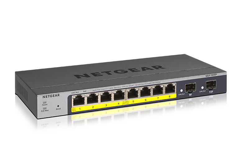
The GS110TP v3 is a 8 + 2-port Gigabit L2 switch with up to 55 Watts of PoE+ power on the 8 Gigabit ports.
Hardware
- RTL8380M SoC
- Winbond W25Q256JVFQ (32MB flash)
- Winbond W631GG8MB (128MB DDR3 SDRAM)
- RTL8231 GPIO extender to control the port LEDs, system LED and a reset button.
- Nuvoton ARM microcontroller
- Broadcom BCM59121B0KMLG PoE controller
Power is supplied via a 54V 1.25A barrel connector.
A Serial header is found at J1. Pins are Vcc(3.3V, Square), TX, RX and GND. Serial connection is via 115200 baud, 8N1.
Ports 1-8 can also provide power according to 802.3.at (PoE+) and PoE is controlled by the BCM59121. PoE management is done by an auxiliary Nuvoton M0516LDN microcontroller. Communication with the Poe-CPU happens via a serial port, connected to the main CPU's UART1. Optocouplers are used to isolate the two circuits from each other and the communication frames can be sniffed from J3 (3.3V, 19200 baud, 8n1).
To indicate the global device status, two LEDs are present on the front panel. One is labelled 'PoE Max', and is likely controlled directly by the PoE MCU. The other is labeled 'Power', and is used to indicate the device status. This LED appears to be an RGB LED, although it is currently unclear how the three colours are controlled. All ports have a two-pin bi-color LED, used to indicate the link status: green for 1000M, orange for 100M. These are driven by three SN74HC164 shift registers, using 20 of the 24 outputs available. PoE status bi-color LEDs are also available, with green used to indicate the remote device is PoE powered, and orange to signal a PoE fault status. The PoE-status LEDs are driven by two SN74LV595A shift registers, also controlled by the PoE MCU.
There is also a SN74LVC125A four-port tri-state buffer whose purpose is currently unknown.
Board pictures


Pinouts
Serial console
- J1.1: 3.3V via R9 (not populated)
- J1.2: RX
- J1.3: TX
- J1.4: GND
Serial PoE control
This connector is in the PoE power domain, which is isolated from the power domain of the SoC. Be careful when connecting to this port and use a digital isolator.
- J3.1: VCC (appears not connected)
- J3.2: RX
- J3.3: TX
- J3.4: GND
References
- Product page: https://www.netgear.com/support/product/GS110TPv3