The IceCube LED display built at UGent was based on the mechanical designs of the UW River Falls displays, but uses the icecube-display firmware instead of the Teensy's Arduino interface used in the original design. It is a scale 1:500 display, so is approximately \((2m)^3\) in size, and is driven by three Teensy 3.2 ARM microcontroller development boards.
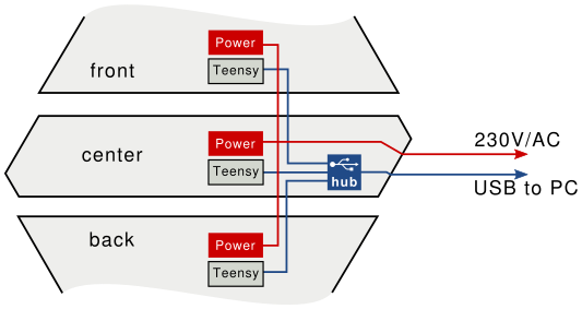
The full IceCube detector was broken up into three display modules to facilitate transport, each containing a Teensy board. Provided there is a way to mechanically support the upper part of the module, each of the modules can be controlled as an independent display that supports part of the IceCube detector.

A single module contains roughly one third of the IceCube strings. At 60 DOMs per string, this equates to up to 1800 RGB LEDs that can draw 60mA at 5V when set to full brightness. Therefore two 5V-60A power supplies (HRP-300-5) are used in each module to power the LEDs.
To reduce the number of cables running to the fully assembled display, the front and back modules can get their USB connection to the PC via the center module. To achieve this, the center module contains a USB hub whose upstream port is accessible from the side of the module. Two downstream USB ports are provided facing the front and back modules. A multi-TT hub was used to provide optimal throughput on the high-speed USB connection leading to the hub.
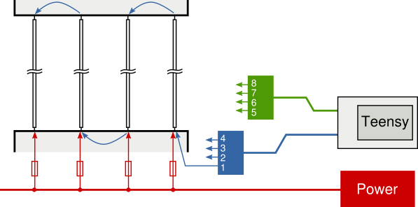
All the electronics are located in the bottom part of the module. The top part only contains a small amount of cabling to connect data lines of the LED strips (see next section).

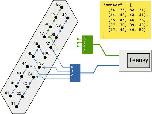
The Teensy controllers use an 8-bit port to send serial data to 8 LED strips simultaneously. To make these output pins easily accessible, the Teensys are seated in a OctoWS2811 adaptor. The two RJ45 connectors are then each fed to a splitter board using CAT5e cables to provide 8 strip ports. Since 8 ports is smaller than the corresponding number of IceCube strings per display segment, the data lines of up to four LED strips are connected in series, resulting in a strip with 60 to 240 LEDs. The data lines for the first and third strip run from bottom to top, while the data lines for the second and fourth strip run from top to bottom. Connections between the strips are made inside the display segment boxes and do not change between different assemblies of the display. Each strip of 60 LEDs is powered through the bottom case and is equipped with a circuit breaker, rated to 4A, to prevent one short circuit from taking down half the display segment.

The way the LED strips are grouped is not predetermined and depends on the length of the available connecting cables, location of the microcontroller inside the module's bottom box, and of course personal preferences of the person doing the cabling. Therefore, the strip configuration is stored in the microcontroller's EEPROM such that the same firmware can be used in different displays. The below figure shows an example layout of the center module, with the corresponding JSON snippet that can be used to generate the EEPROM data.

The full JSON file may look as the example provided below. Note that not all display segments use all 8 output ports, and not all ports have 4 strips connected in series. If ports with less than 4 strips are present, the available ports should be populated starting with the longest strips. In the example below, the 'front' module's first seven ports have four strips, and the last port only has two. The 'center' and 'back' modules respectively have four and seven ports used for four strips, and none on the last port(s).
A utility is provided (teensy/update_string_config.py) to generate and upload the EEPROM data starting from this JSON file. Note that after uploading a new configuration, the device should be power cycled for changes to take effect.
To build the firmware, arm-none-eabi-gcc is required. It also uses the newlib C library implementation and a few headers provided by the upstream Teensy repositories for compatibility with some avr-libc functionality.
5 bytes of EEPROM are used to store the display specific properties. The first and last supported string number denote a continous, inclusive range of IceCube strings that can be displayed by the device.
| Address offset | Description |
|---|---|
| 0x20 + 0x0 | Supported LED type: see display_led_type_t |
| 0x20 + 0x1 | LED RGB order: see display_led_color_order_t |
| 0x20 + 0x2 | First supported IceCube string number (in range 1-78) |
| 0x20 + 0x3 | Last supported IceCube string number (in range 1-78) |
| 0x20 + 0x4 | Support for DeepCore strings (boolean) |
Starting from offset 0x30, \(4\times(1+8)\) bytes are used to store the LED strip mapping. The first of each of these nine bytes indicates how many values in the following 8-byte array are valid. Although the number of valid strip segments is stored in the array, care should be taken that mappings for non-existent LED strip segments don't go outside of the supported IceCube string count. In case the firmware would want to read out these offsets anyway, it would re-use LED data from other strings and be prevented from reading possibly invalid data.
The EEPROM segment below corresponds to the above center display segment. The first LED strip on the second port maps to IceCube string \(44=31+\text{D}_{16}\). Note that the EEPROM segment is essentially a transpose of the table provided in the configuration file segment. The three last bytes (unused) of the segment mappings are shown here as '00', as per the recommendation not to use non-existent buffer offsets.
| Address offset | Data (hexadecimal) | |
|---|---|---|
| Ports used | Buffer mapping | |
| 0x30 + 0 | 05 | 03 0D 04 06 10 00 00 00 |
| 0x30 + 9 | 05 | 02 0C 0E 07 11 00 00 00 |
| 0x30 + 18 | 05 | 01 0B 0F 08 12 00 00 00 |
| 0x30 + 27 | 05 | 00 0A 05 09 13 00 00 00 |
To update the firmware on the Teensy, just press the program button. lsusb should now show the Halfkay bootloader:
$ lsusb | grep -e "Teensy"
Bus 003 Device 102: ID 16c0:0478 Van Ooijen Technische Informatica Teensy Halfkay Bootloader
The new firmware can now be uploaded via make upload when building from source, or using the teensy_loader_cli utility when programming a compatible .hex file:
# Only one device can be programmed at a time
teensy_loader_cli --mcu=mk20dx256 -w icecube_display.hex
When a new Teensy is used to run this firmware, or the Teensy has been used for other applications before, the EEPROM will not yet be properly initialised. After programming the device firmware, the upload_eeprom target can be used to upload the device's EEPROM file. After a reset, the device will now be able to read out sensible EEPROM values and be ready for use.
The prices list below do not include VAT. Total estimate (without labor costs) for the UGent display is ~€3000. The UW River Falls cost estimate was $4000, mainly due to more expensive LED strips.