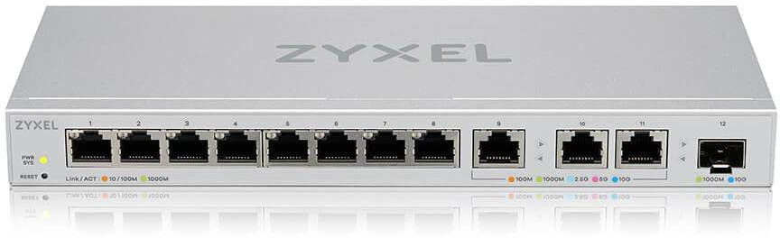
Zyxel XGS1250-12
The XGS1250-12 is a 11 + 1-port Multi-Gigabit L3 switch. It has 8 Gigabit ports, three 2.5/5/10GBit Ethernet ports and one SFP+ 10GBit uplink cages.
Hardware
- RTL9302B SoC
- Macronix MX25L12833F (16MB flash)
- Winbond W613GU6MB-12 (128MB DDR3 SDRAM)
- RTL8231 expander in shift register mode for the port LEDs
- 8×GbE via RTL8218D PHY
- 3× AQR113C NBase-T PHYs
- One SFP+ uplink port
Power is supplied via a 12V 2A standard barrel connector. At the right side behind the grid is UART serial connector. A Serial header can be connected to from the outside of the switch trough the airvents with a standard 2.54mm header. Pins are from top to bottom Vcc(3.3V), TX, RX and GND. Serial connection is via 115200 baud, 8N1.


JTAG
The board has an unpopulated eJTAG header J2. Similar to the GS1900-48, nSRST and nTRST are configured such that the port is disabled. The following modifications make use of the eJTAG port possible:
- Add jumper across R155 to connect the nSRST pin.
- Move R156 to R151 to change the permanent pull-down into a pull-up.
- (optional) Modify the heatsink and add a 2×7 pin header (see picture)
The header's VIO pin is a voltage reference, tied to VCC via a 1k resistor (R153). This pin cannot be used to source current and is only provided as voltage reference.

Port numbers
The RTL9302 SoC supports 24 GbE ports, and four 10G ports.
Device ports 1-8 are switch ports 0-7. Device ports 9-12 are switch port 24-27.
| Ports | LED index | LED comment |
|---|---|---|
| 1-8 | 0 | Amber component of anti-parallel amber/lime LED. LED0 must be off. |
| 1-8 | 1 | Green component of anti-parallel amber/lime LED. LED1 must be off. |
| Ports | LED index | LED comment |
| 9-11 | 0 | Multi-LED selection. 0 chooses the lime/amber LEDs. 1 chooses the RGB LEDs. |
| 9-11 | 1 | LED0 = 0: amber, LED0 = 1: red |
| 9-11 | 2 | LED0 = 0: lime, LED0 = 1: green |
| 9-11 | 3 | LED0 = 0: (none), LED0 = 1: blue |
| Ports | LED index | LED comment |
| 12 | 0 | Blue |
| 12 | 1 | Lime |
Board details
------------------ Board Configuration ------------------

****************************
 ZYXEL XGS1250-12
****************************
============================
 Board GPIO
============================
Device  Pin  Direction  Default  Current  Purpose
------- ---- ---------- -------- -------- --------
INT     0    OUT        0        0
INT     1    IN         1        1        FAN_CONTROL
INT     6    IN         1        0        HW_VER_BIT1
INT     7    IN         1        1        HW_VER_BIT0
INT     11   OUT        0        0        FAN_EN
INT     15   OUT        0        0        TX_DIS_P11
INT     16   IN         0        1        SFP_Present_P11
INT     17   IN         0        1        SFP_LOS_P11
INT     20   IN         0        0        TX_FAULT_P11
INT     21   OUT        1        1        RESET_PHY
INT     22   IN         1        1        RST_BTN_OUT

============================
 Board Configuration
============================
====== Port ==================
Type        Usr  Phy     Media       Speed          Duplex   Attr
----------- ---- ------- ----------- -------------- -------- -------
1000M       1    (0) 0   Copper      (A) ALL        Auto     0
1000M       2    (0) 1   Copper      (A) ALL        Auto     0
1000M       3    (0) 2   Copper      (A) ALL        Auto     0
1000M       4    (0) 3   Copper      (A) ALL        Auto     0
1000M       5    (0) 4   Copper      (A) ALL        Auto     0
1000M       6    (0) 5   Copper      (A) ALL        Auto     0
1000M       7    (0) 6   Copper      (A) ALL        Auto     0
1000M       8    (0) 7   Copper      (A) ALL        Auto     0
10G         9    (0) 24  Copper      (A) ALL        Auto     0
10G         10   (0) 25  Copper      (A) ALL        Auto     0
10G         11   (0) 26  Copper      (A) ALL        Auto     0
10G         12   (0) 27  Fiber       (F) 10G        (F) Full 0


====== Fiber =================
Fiber Port Number: 1

------------ Fiber Detect
LPort  Present  MediaChg  OE Status              LOS Status
------ -------- --------- ---------------------- ----------------------
11     OE       None      Enabled  (GPIO:INT_16) Enabled  (GPIO:INT_17)

------------ Fiber Optical
LPort  I2C DEV  I2C TYPE  ID    Delay   SCK    SDA
------ -------- --------- ----- ------- ------ ------
11     2        8 BITS    0x50  50      INT_8  INT_10

------------ Fiber TX Disable
LPort  Method
------ ------
11     GPIO(INT_15)


====== Button ================

------------ Reset Button
GPIO: INT_22
Timer: 3(sec)  Action: Reboot
Timer: 6(sec)  Action: Restore Factory


====== Led ===================
SYSTEM
  ON [ASIC(G)]
  OFF [ASIC(G)]
  BLINK [ASIC(G)]
Port
  ON [ASIC(P)]
  ON C2 [ASIC(P)]
  OFF [ASIC(P)]
  AUTO [ASIC(P)]


====== Reset =================
Type: GPIO
GPIO: INT_21


====== WatchDog ==============
Type: REG