This is an old revision of the document!
Netgear GS310TPv1
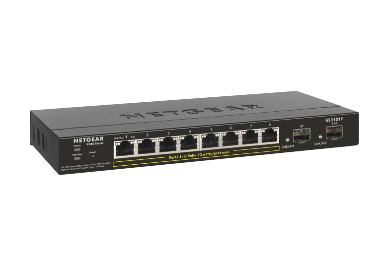
The GS310TPv1 is a 8 + 2-port Gigabit L2 switch with up to 55 Watts of PoE+ power on the 8 Gigabit ports. It is part of the Netgear S350 Series.
Hardware
- RTL8380M SoC
- Winbond W25Q256JVFQ (32MB flash)
- Winbond W631GG8MB (128MB DDR3 SDRAM)
- RTL8231 GPIO extender to control the port LEDs, system LED and a reset button.
- Nuvoton ARM microcontroller
- Broadcom BCM59121B0KMLG PoE controller
Power is supplied via a 54V 1.25A barrel connector.
A Serial header is found at J1. Pins are Vcc(3.3V, Square), TX, RX and GND. Serial connection is via 115200 baud, 8N1.
Board details

Pin-outs
Serial console
- J1.1: 3.3V via R9 (not populated)
- J1.2: RX
- J1.3: TX
- J1.4: GND
Serial PoE control
This connector is in the PoE power domain, which is isolated from the power domain of the SoC. Be careful when connecting to this port and use a digital isolator.
- J3.1: VCC (appears not connected)
- J3.2: RX
- J3.3: TX
- J3.4: GND
Firmware
The switch ships with a bootloader based on Realtek's SDK for RTL83xx SoCs and Linux based on Realtek's SDK. It has a web interface for basic management, including firmware updates. The board identifies as RTL8393M_DEMO. But this is misleading. The SoC chip id is 83806800, which is RTL8380M_CHIP_ID according to sdk/include/hal/chipdef/chip.h in Realtek's SDK.
| Flash layout | |||||||
|---|---|---|---|---|---|---|---|
| Name | u-boot | u-boot-env | device-info | config | log | firmware1 | firmware2 |
| Size | 896k | 64k | 64k | 1M | 1M | 14.5M | 14.5M |
Vendor board definition
------------------ Board Configuration ------------------

***********************************************************
 S350 Series 8-Port Gigabit PoE+ Ethernet Smart Managed Pro Switch with 2 SFP Ports
***********************************************************
============================
 Board GPIO
============================
Device  Pin  Direction  Default  Current
------- ---- ---------- -------- --------
EXT     31   OUT (OUT ) 1        0
EXT     32   OUT (OUT ) 0        1
EXT     35   OUT (OUT ) 1        1
EXT     33   OUT (OUT ) 0        0
EXT     34   OUT (OUT ) 1        1
EXT     24   OUT (OUT ) 1        1
INT     0    IN         0        1
EXT     20   OUT (OUT ) 1        1
INT     13   OUT        1        1
EXT     25   OUT (OUT ) 1        1
EXT     10   OUT (OUT ) 0        1
EXT     7    IN  (IN  ) 0        1
EXT     6    IN  (IN  ) 0        1
INT     16   IN         0        1
INT     15   IN         0        0
EXT     14   IN  (IN  ) 0        1
EXT     13   IN  (IN  ) 0        1
INT     18   IN         0        1
INT     17   IN         0        1
EXT     28   OUT (OUT ) 0        0
EXT     27   OUT (OUT ) 0        1
EXT     11   IN  (IN  ) 0        0
EXT     11   IN  (IN  ) 0        0
EXT     5    IN  (IN  ) 0        0
EXT     4    IN  (IN  ) 0        0
EXT     12   IN  (IN  ) 0        0

============================
 Board Configuration
============================
====== Port ==================
Type        Usr  Phy     Media       Speed          Duplex   Attr
----------- ---- ------- ----------- -------------- -------- -------
1000M       1    (0) 8   Copper      (A) ALL        Auto     1
1000M       2    (0) 9   Copper      (A) ALL        Auto     1
1000M       3    (0) 10  Copper      (A) ALL        Auto     1
1000M       4    (0) 11  Copper      (A) ALL        Auto     1
1000M       5    (0) 12  Copper      (A) ALL        Auto     1
1000M       6    (0) 13  Copper      (A) ALL        Auto     1
1000M       7    (0) 14  Copper      (A) ALL        Auto     1
1000M       8    (0) 15  Copper      (A) ALL        Auto     1
1000M       9    (0) 24  Fiber       (A) ALL        Auto     0
1000M       10   (0) 26  Fiber       (A) ALL        Auto     0


====== Fiber =================
Fiber Port Number: 2

------------ Fiber Detect
LPort  Present  MediaChg  OE Status              LOS Status
------ -------- --------- ---------------------- ----------------------
8      OE       OE        Enabled  (GPIO:EXT_14) Enabled  (GPIO:EXT_7 )
9      OE       OE        Enabled  (GPIO:EXT_13) Enabled  (GPIO:EXT_6 )

------------ Fiber Optical
LPort  I2C DEV  I2C TYPE  ID    Delay   SCK    SDA
------ -------- --------- ----- ------- ------ ------
8      0        8 BITS    0x50  1000    EXT_36 EXT_28
9      1        8 BITS    0x50  1000    EXT_36 EXT_27

------------ Fiber TX Disable
LPort  Method
------ ------
8      GPIO(EXT_28)


====== Button ================

------------ Reset Button
GPIO: INT_0
Timer: 3(sec)  Action: Reboot
Timer: 5(sec)  Action: Restore Factory


====== Led ===================
System (GPIO) GPIO: EXT_31
Alarm (GPIO) GPIO: EXT_32
Port Green (ASIC)Port Yellow (ASIC)

====== Reset =================
Type: GPIO
GPIO: INT_13


====== WatchDog ==============
Type: REG


====== PoE ===================
Bootloader
U-Boot is used as bootloader for this device, and has access to a modifiable u-boot-env partition. This can be used to store modified and custom environment variables.
Some realtek-specific commands are also available:
rtk network on: Configure the ethernet hardware inside the bootloader (not enabled on boot).