Netgear GS108Tv3
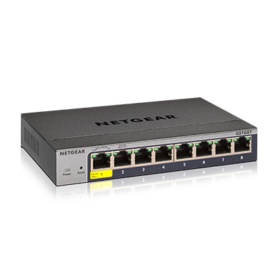
The GS108Tv3 is a 8-port Gigabit L2 switch with optional 802.3af PD power input on port 1.
Hardware
- RTL8380M SoC
- Macronix MX25L25635F (32MB flash)
- Winbond W631GG8MB (128MB DDR3 SDRAM)
- RTL8231 GPIO extender to control the port LEDs, system LED and a reset button.
Power is supplied via a 12V 1A barrel connector or 802.3af.
A Serial header is found at J1. Pins are Vcc(3.3V, Square), TX, RX and GND. Serial connection is via 115200 baud, 8N1.
Board details


Pin-outs
SoC UART
- J1.1: VCC, 3.3V (square pad)
- J1.2: RX
- J1.3: TX
- J1.4: GND
Firmware
The switch ships with a bootloader based on Realtek's SDK for RTL83xx SoCs and Linux 3.18 based on Realtek's SDK. It has a web interface for basic management, including firmware updates. The web interface must be unlocked to gain access to all management functions. The unlock key is provided after registering the product with Netgear. The board identifies as RTL8393M_DEMO. But this is misleading. The SoC chip id is 83806800, which is RTL8380M_CHIP_ID according to sdk/include/hal/chipdef/chip.h in Realtek's SDK.
| Flash layout | |||||||
|---|---|---|---|---|---|---|---|
| Name | u-boot | u-boot-env | device-info | config | log | firmware1 | firmware2 |
| Size | 896k | 64k | 64k | 1M | 1M | 14.5M | 14.5M |
Vendor board definition
------------------ Board Configuration ------------------

***********************************************************
 GS108Tv3 8-Port Gigabit Smart Managed Pro Switch
***********************************************************
============================
 Board GPIO
============================
Device  Pin  Direction  Default  Current
------- ---- ---------- -------- --------
EXT     31   OUT (OUT ) 1        0
EXT     32   OUT (OUT ) 0        1
EXT     34   OUT (OUT ) 1        1
EXT     24   OUT (OUT ) 1        1
INT     0    IN         0        1
EXT     20   OUT (OUT ) 1        1
INT     13   OUT        1        1
EXT     25   OUT (OUT ) 1        1
EXT     10   OUT (OUT ) 0        0
EXT     7    IN  (IN  ) 0        0
EXT     6    IN  (IN  ) 0        0
EXT     14   IN  (IN  ) 0        0
EXT     13   IN  (IN  ) 0        0
EXT     9    OUT (OUT ) 0        0
EXT     8    OUT (OUT ) 0        0
EXT     11   IN  (IN  ) 0        0
EXT     4    IN  (IN  ) 0        0
EXT     12   IN  (IN  ) 0        0

============================
 Board Configuration
============================
====== Port ==================
Type        Usr  Phy     Media       Speed          Duplex   Attr
----------- ---- ------- ----------- -------------- -------- -------
1000M       1    (0) 8   Copper      (A) ALL        Auto     0
1000M       2    (0) 9   Copper      (A) ALL        Auto     0
1000M       3    (0) 10  Copper      (A) ALL        Auto     0
1000M       4    (0) 11  Copper      (A) ALL        Auto     0
1000M       5    (0) 12  Copper      (A) ALL        Auto     0
1000M       6    (0) 13  Copper      (A) ALL        Auto     0
1000M       7    (0) 14  Copper      (A) ALL        Auto     0
1000M       8    (0) 15  Copper      (A) ALL        Auto     0


====== Button ================

------------ Reset Button
GPIO: INT_0
Timer: 2(sec)  Action: Reboot
Timer: 5(sec)  Action: Restore Factory
Timer: 10(sec)  Action: ^B


====== Led ===================
System
  ON [GPIO(D)]
  ON C2 [GPIO(D)]
  OFF [GPIO(D)]
Port
  ON [ASIC(P)]
  ON C2 [ASIC(P)]
  OFF [ASIC(P)]
  AUTO [ASIC(P)]
PoE Max
  ON []
  OFF []
  AUTO []
PoE Port
  ON []
  ON C2 []
  OFF []
  AUTO []


====== Reset =================
Type: GPIO
GPIO: INT_13


====== WatchDog ==============
Type: REG
Bootloader
U-Boot is used as bootloader for this device, and has access to a modifiable u-boot-env partition. This can be used to store modified and custom environment variables.
Some realtek-specific commands are also available:
rtk network on: Configure the ethernet hardware inside the bootloader (not enabled on boot).