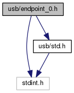
USB Endpoint 0 state machine interface. More...

Go to the source code of this file.
Data Structures | |
| struct | control_transfer_t |
| Control transfer state tracking. More... | |
Enumerations | |
| enum | control_stage_t { CTRL_IDLE, CTRL_SETUP, CTRL_STALL, CTRL_DATA_IN, CTRL_DATA_OUT, CTRL_HANDSHAKE_IN, CTRL_HANDSHAKE_OUT, CTRL_POST_HANDSHAKE } |
| Constants used to indicate the default control endpoint's current state. More... | |
| enum | vendor_request_t { VENDOR_REQUEST_PUSH_FRAME = 1, VENDOR_REQUEST_DISPLAY_PROPERTIES = 2, VENDOR_REQUEST_EEPROM_WRITE = 3, VENDOR_REQUEST_EEPROM_READ = 4, VENDOR_REQUEST_FRAME_DRAW_STATUS = 5, VENDOR_REQUEST_FRAME_DRAW_SYNC = 6 } |
Functions | |
| void | process_setup (struct control_transfer_t *transfer) |
| Process setup request for control transfers. More... | |
| void | init_control_transfer (struct control_transfer_t *transfer, const struct usb_setup_packet_t *setup) |
| Initialise the control transfer. More... | |
| void | cancel_control_transfer (struct control_transfer_t *transfer) |
| Change the transfer state to STALL and perform the cancel callback, if any. | |
| void | control_mark_data_done (struct control_transfer_t *transfer, uint16_t length) |
| Mark length bytes of the control transfer as done and perform the data callback. | |
USB Endpoint 0 state machine interface.
Control transfers are usually handled asynchronously via interrupts. When the device has to wait for an answer from the host for example, this means that the firmware won't wait and poll to see if an answer has been received, but resumes normal operation until an interrupt is fired. This implies the use of task specific callbacks, since different setup request require different actions to be performed, possibly at different points in the request's lifetime.
| enum control_stage_t |
Constants used to indicate the default control endpoint's current state.
| enum vendor_request_t |
Vendor specific USB control request for display status and control.
| Request name | bmRequestType | bRequest | wValue | wIndex | wLength |
|---|---|---|---|---|---|
| VENDOR_REQUEST_DISPLAY_PROPERTIES | 0b1_10_00000 | 2 | 0 | 0 | 2-65535 |
| VENDOR_REQUEST_EEPROM_WRITE | 0b0_10_00000 | 3 | 0 | offset | length |
| VENDOR_REQUEST_EEPROM_READ | 0b1_10_00000 | 4 | 0 | offset | length |
| VENDOR_REQUEST_FRAME_DRAW_STATUS | 0b1_10_00000 | 5 | 0 | 0 | 4 |
| VENDOR_REQUEST_FRAME_DRAW_SYNC | 0b0_10_00000 | 6 | [ms] | 0 | 0 |
| Enumerator | |
|---|---|
| VENDOR_REQUEST_PUSH_FRAME | Push a single frame to be shown on the display into the frame buffer queue. When connected via USB all other renderers are stopped, so this frame will be displayed until the next one is pushed. Note that the device only updates the display 25 times per second, so pushing frame more frequently than this will result in buffer overflows on the device and consequently control transfers will be stalled until memory is freed. Since some platforms may not support control transfers of the size needed to send a frame, it is possible to send a single frame using multiple PUSH_FRAME commands.
|
| VENDOR_REQUEST_DISPLAY_PROPERTIES | Request a TLV list of display metadata. A reply to this request will always consist of at least two bytes, which provide the total length of the response. A typical query of this metadata will be done the following way:
|
| VENDOR_REQUEST_EEPROM_WRITE | To perform the (initial) configuration of the device, one may also use the USB interface to read to and write from the microcontroller's EEPROM. EEPROM_READ and EEPROM_WRITE allow access to an EEPROM segment of arbitrary length, starting from any offset address that is within the size of the EEPROM. The wIndex field of the setup request is used to provide the address offset of the EEPROM memory segment that is to be written. A request with Use the EEPROM_WRITE command with care, as writing bad data to the EEPROM may render the device unusable. |
| VENDOR_REQUEST_EEPROM_READ | Read a segment from the device's EEPROM. See VENDOR_REQUEST_EEPROM_WRITE on how to use the wIndex and wLength fields. For example, the IceCube string to buffer offset mapping of IceCube display microcontrollers can be read using |
| VENDOR_REQUEST_FRAME_DRAW_STATUS | Get the latest frame draw time. The request response consists of two unsigned 16 bit (little endian) integers a defined by display_frame_usb_phase_t. |
| VENDOR_REQUEST_FRAME_DRAW_SYNC | Correct the frame counter ms value by the provided amount. The ms correction \(\delta\) is provided as a signed (little endian) 16 bit integer contained in the wValue field of the setup request. Corrections larger than \(\pm(2^{15}-1)\)ms should be performed using multiple requests. In this case the first request should perform the largest possible correction including the full USB frame counter phase slip, i.e. \((\delta \bmod 40) + N \times 40 = \Delta_0\) with \(|\Delta_0| \le 2^{15}-1\). This synchronises the fraw draws down to the millisecond, but leaves the frame counters out of phase. Subsequent requests can then correct the remaining offset as multiples of 40ms. |
| void init_control_transfer | ( | struct control_transfer_t * | transfer, |
| const struct usb_setup_packet_t * | setup | ||
| ) |
Initialise the control transfer.
Sets the transfer stage to SETUP and stores the provided setup packet setup as the corresping request for the transfer.
| void process_setup | ( | struct control_transfer_t * | transfer | ) |
Process setup request for control transfers.
The transfer object is updated with the correct information to continue processing the control transfer. In case this is a valid and recognised setup packet, transfer->stage will be updated to the state the transfer is in once this function returns. If the control transfer stage is still CTRL_SETUP when this function returns, the request should be considered invalid and the control endpoint stalled.